How To do A serial loopback test??
A loopback test allows you to send and receive data from the same serial port to verify that the port is operational. To perform this test, you need to temporarily connect the proper pins to allow signals to be sent and received on the same port.
Table of Contents
Loopback Test
A loopback test can be used to troubleshoot serial communications. It can show problems in the serial port, the cable, or the software generating the messages without having to connect to third party hardware. By connecting the proper wires, a loopback test can verify the operation of serial communication. Loopback tests can be used for RS-232, RS-422, and RS-485 serial communication.
For more information on RS-232, RS-422, and RS-485 see the Serial Communication Overview. Note that not all serial devices, especially those with many connections on one card, allow hardware flow control on every serial output of the device.
To perform a loopback test for RS-232, the TXD pin must be connected to the RXD pin. This allows the data to flow from the transmit to the receive pins. Since the communication is differential for RS-422 and RS-485, the TXD+ connects to the RXD+ and the TXD- connects to the RXD- pins.
A more advanced loopback test that allows hardware flow control will need more pins connected to allow the flow control signals to be properly passed. For RS-232, the CTS and RTS pins must be connected along with the DTR and DSR pins. For RS-422 and RS-485, CTS+ should be connected to RTS+ and CTS- should be connected to RTS-.
For more information about National Instrument’s serial interfaces, visit ni.com/serial.
Connectors
DE-9 (DB9) Connector
The DE-9 connector is the most common serial connector. This connector is found on National Instrument’s one and two port serial interfaces.

Figure 1: Pinout diagram for DE-9 Connector
To perform a loopback test with no hardware flow control, you will need to connect pins 2 and 3 for RS-232 and pins 4 to 8 and 5 to 9 for RS-422/485. These connections can be seen in redbelow (figure 2 for RS-232 and figure 3 for RS-422/485).
When using hardware flow control, you will need to connect pins 4 to 6 and 7 to 8 for RS-232. Pins 7 and 8 are used for RTS/CTS hardware flow control where pins 4 and 6 are used for DTR/DSR hardware flow control. For RS-422/485, you will need to connect pins 2 to 3 and 6 to 7. Both of these connections are required for RTS/CTS hardware flow control since RS-422/485 have differential connections. These connections can be seen in blue below (figure 2 for RS-232 and figure 3 for RS-422/485).

Figure 2: RS-232 female DE-9 plug with connections required for loopback test

Figure 3: RS-422/485 female DE-9 plug with connections required for loopback test
DB-25 Connector
This connector is not as common as the DE-9 connector. This connector can still be used to perform a loopback test with a method similar to the one used for the DE-9 connector.
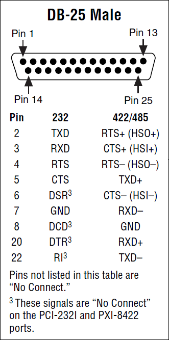
Figure 4: Pinout diagram for DB-25 Connector
Most of the pins on DB-25 connectors are not connected since only nine pins are used for RS-232, RS-422, and RS-485 communication.
To perform a loopback test with no hardware flow control with a DB-25 connector, connect pins 2 to 3 for RS-232. For RS-422/485 connect pins 5 to 20 and 7 to 22. The required connections can be seen in red on figures 5 and 6.
For hardware flow control using RS-232, pins 4 and 5 must be connected along with pins 6 and 20. When using RS-422/485, pin 5 must connect to pin 20 and pin 7 must connect to pin 22. This will allow the loopback test to use the proper flow control lines. These connections can be seen in blue on figures 5 and 6.
Figure 5: RS-232 female DB-25 plug with connections required for loopback test
Figure 6: RS-422/485 female DB-25 plug with connections required for loopback test
10P10C (RJ50) Connector
This connector is most commonly found on National Instrument’s 4 port serial interfaces. The National Instrument 4 port serial interfaces come with 4 10P10C to DE-9 male converter cables.
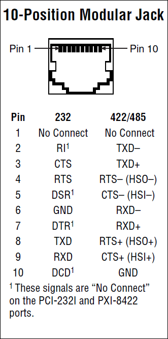
Figure 7: Pinout diagram for RJ50 Connector
It is not recommended to use the 10P10C connector by itself to perform a loopback test due to the small separation between pins. Using a 10P10C to DE-9 connector (Part Number 192190-01), a looback test can be performed using the methods described above.
Performing a Loopback Test in Hyperterminal
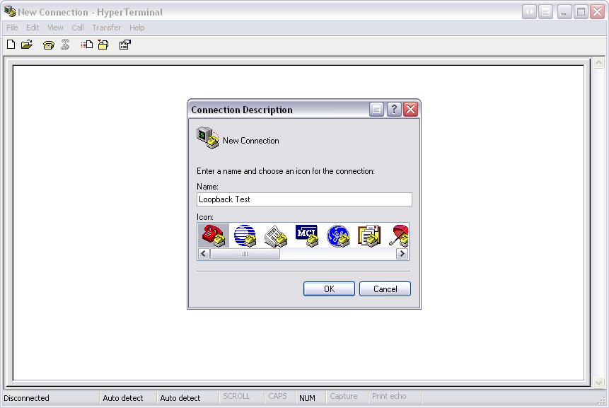
1. Create a new connection with any name and icon.
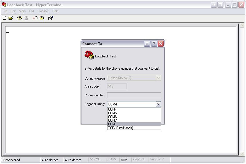
2. Select the communications port you would like to test
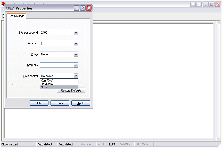
3. Select the type of flow control you would like to use. Note that Xon / Xoff is software flow control and will only require that the TXD and RXD pins to be connected.
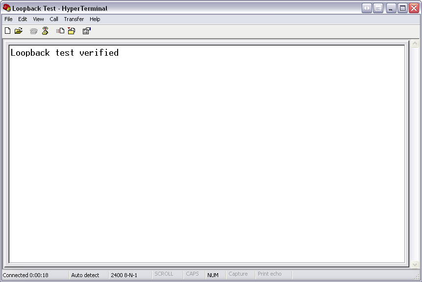
4. Type a message using the computer's keyboard. Any data that shows in Hyperterminal is received from the device.
Performing a Loopback test in Measurement & Automation Explorer
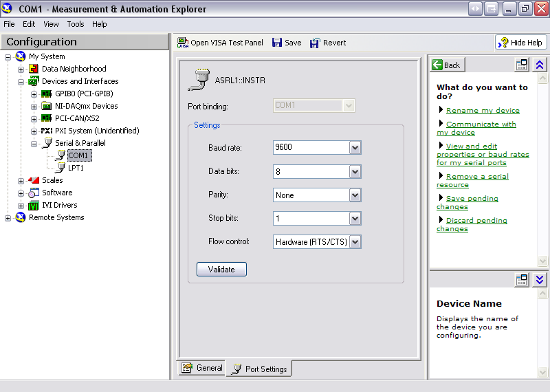
1. Open Measurement & Automation Explorer and select the communications port you would like to use.
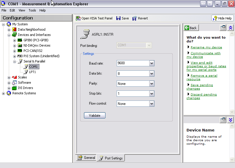
2. Ensure the proper settings are selected for flow control.

3. Save the settings by selecting the Save button then select the Open VISA Test Panel button
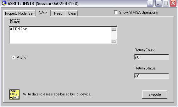
4. On the Write tab, type the message you would like to send (followed by a \n) then selectExecute
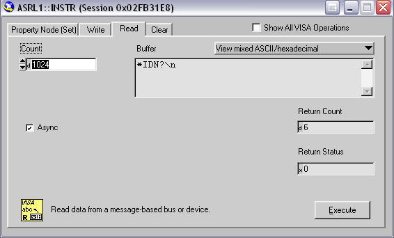
5. On the Read tab, select Execute and verify the message
Performing a Loopback test in LabVIEW
Note: For a free evaluation copy of LabVIEW, visit ni.com/trylabview
1. Start LabVIEW
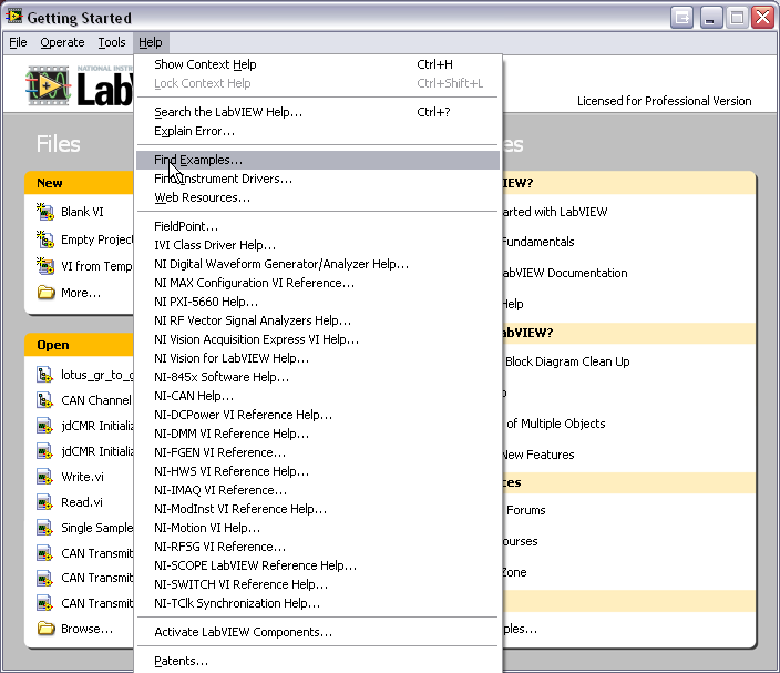
2. Select Help»Find Examples...
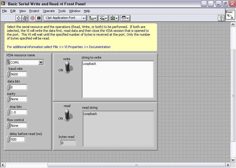
3. Browse to Hardware Input and Output»Serial»Basic Serial Write and Read.vi
Comments
Post a Comment